In general, the CPU core development requires far more man-hours for the verification phase than the design. This is because there are a huge number of items to be verified, such as the instruction sequences, the combination of exceptions, and the error occurrences. This blog introduces an example of RISC-V core UVM verification that Verification Technology USA, Inc. (Vtech) provided a startup company in the US as a service.
The customer designed the RISC-V core’s RTL and the entire SoC in parallel. There was a shortage of resources, and Vtech covered the verification for the RISC-V. The RISC-V core to be verified was intended for use in edge devices, and the instruction set supported RV32I, RV32E, M-Extension, and C-Extension.
Vtech set up a verification team led by an engineer with deep knowledge of MIPS CPUs. The team also had a member that created a C-model of the RISC-V core and another member that performed verification. The two teams aimed to improve the verification quality by checking the results with each other.
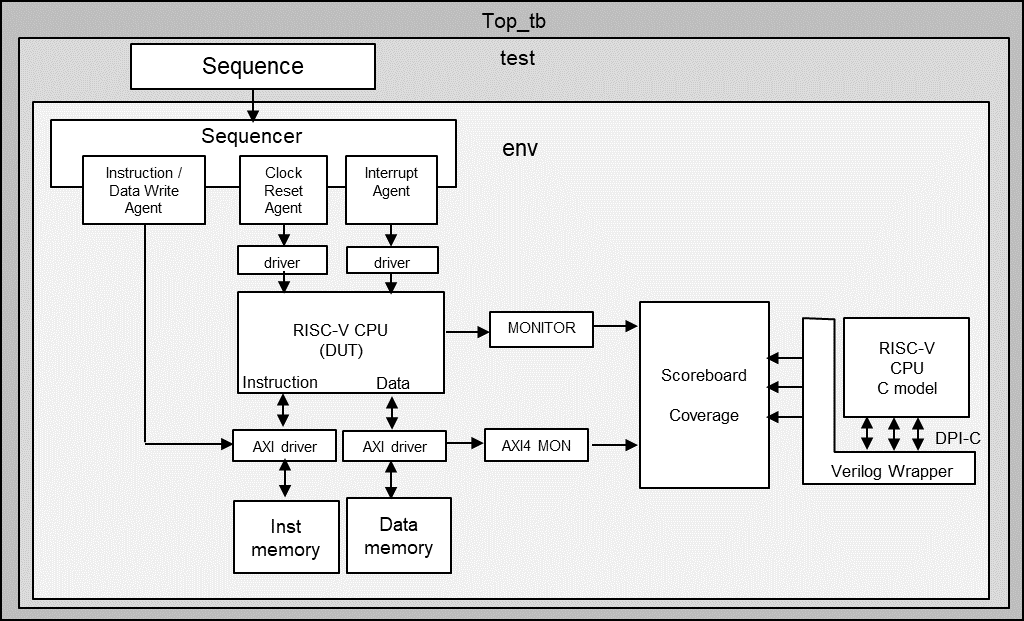
The simulation environment shown in Fig. 1 was developed from scratch with UVM. It incorporates a C-model (ISS level) newly developed in-house and compares the behavior of the RISC-V CPU RTL (DUT) with the C model.

Fig. 1
As a simulation environment for the CPU core, there is also a method to build a simulation environment that can load and execute objects generated by the C compiler or assembler. But in this project the environment was built entirely with UVM, and all instruction sequences executed by the RISC-V core were also created as UVM scenarios. This was because they can be described by combining random generation and manual designation of instruction sequences, such as directly describing specific instruction sequences or randomly generating a part of instruction codes and operands. The coverage of the executed instruction can be also gained.
The C model was newly developed by Vtech for this project by referring to the RISC-V instruction set documentation (ISA Specification). Instruction execution, memory access, interrupt processing, etc. were implemented, and it was called from the testbench using DPI-C and operated as follows.
- Called back the function on the SystemVerilog side from the C model to fetch instructions and access data. The corresponding function / task accesses resources such as memory in the simulation environment.
- Called back the task on the SystemVerilog side even when the value of the Program Counter, PC, or register changes to compare the values on the RTL side of the testbench.
- Output log file of instruction execution and data access trace information for debugging.
Writing the instruction sequence data generated in the scenario to the Instruction Memory and Data Memory in the test bench, and then releasing the CPU reset, the CPU started operating. The CPU and C model operated synchronously on an instruction-by-instruction basis. Since the C model was completed the instruction execution first (because it is at the ISS level), the data access information from the C model and the changed information of the PC and internal registers are recorded in the queue. The PC and register values on the RTL side were compared when the instruction execution was completed, and the address data at the time of memory access was compared when the AXI bus transaction was completed.
We obtained coverage for all the scenarios we created and confirmed that all instruction codes and operands were tested. We also examined sequences of the multiple instructions that are affected by the pipeline structure. The sequences of mixed instructions by load, store, arithmetic instruction, branch instruction, CSR, etc. were automatically generated. In these instruction sequences, there were combinations such as when the register operands of each instruction were the same or different, when the branch conditions were met or not met, and so on. In addition, we also verified when wait cycles were inserted into instruction fetch or data bus access cycles, when bus error occurred, and when exception or interrupt occurred between instructions. It was confirmed that the combination of these multiple instructions and that of external signals (wait cycle requests, interrupts, etc.) could be tested as intended in the coverage.
The project lasted 8 months and allowed the RISC-V core to tape-out on time with a successful first pass.